
Danyon Dupie Cyber-Security Project Website
Smart Home Automation Prototype Project
Develop a smart home automation and security system by designing the prototype and programming using a virtual emulator. The smart home system will encompass various devices to monitor the condition of the home. This includes a door sensor to check whether to door is open or closed, a distance sensor to monitor for a home intruder, and automated lights that turn on when it is dark. Optional components can be added to the smart home system including a water level sensor to monitor for flooding and a temperature and humidity sensor to monitor the weather.
Introduction
Hello and welcome to my Smart Home Automation Prototype Project that I built at during my studies at DeVry University. The goal of the project was to create a design of a protype and simulate a smart home security system using Tinkercad. Tinkercad offers many
benefits: First, it’s browser-based so you do not need to install anything on your PC, you just need the internet. Second, it’s open source so it’s free for everyone but you do however need to set up an account. Finally, it’s best feature of all is that it is a simulator which provides a good interface for designing your project. Objective of this project was to create a comprehensive smart home automation and security system that enhances home safety and convenience.
Scenario
Develop a smart home automation and security system by designing the prototype and programming using a virtual emulator. The smart home system will encompass various devices to monitor the condition of the home. This includes a door sensor to check whether to door is open or closed, a distance sensor to monitor for a home intruder, and automated lights that turn on when it is dark. Optional components can be added to the smart home system including a water level sensor to monitor for flooding and a temperature and humidity sensor to monitor the weather.
Tools that were used during this project:
C++
Arduino UNO R3
Breadboard
LED lights
Resistor 10kΩ
•Photoresistor
•Wires
•USB to Type B Cable
•DHT – 11 sensor
•Water level sensor
•Passive buzzer (used to sound an alarm to scare off intruders)
•Slide switch (emulate home entrance door)
•Ultrasonic sensor
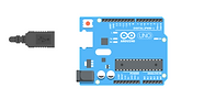
Aruduino UNO R3

Breadboard

LED Lights


Photoresistor

SlideSwitch
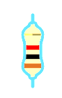
Resistor
Ultrasonic Sensor
Step 1: Circuit Simulation
Goal:
-
To introduce simulation using a virtual emulator
-
To familiarize with hardware components required to build physical systems
-
To familiarize with programming logic and design of hardware
-
To familiarize with error handling principles in operating systems
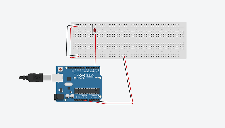
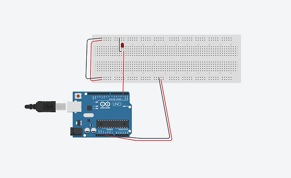
For this part of the project, what I did was connect the Arduino Uno R3 to the Breadboard. The Arduino R3 is my smart hub for the home security system in Tinkercad and it is the most used and documented microprocessor board of the whole Aruduino family. Contains everything needed to support the microcontroller including 14 digital input/output pins (6 can be used as PWM outputs), 6 analog, a 16 MHZ ceramic resonator, a USB connection, a power jack, an ICSP header and a reset button. Breadboard is a opton that employs the best practice to always connect 5V and ground these long rails as a starting point for any Arduino circuit. Notice the wire connecting Arduino's 5V pin with the red (+) power rail on the breadboard, and likewise GND with the black (-) ground rail. Notice that the power and ground rails are extended to their respective rails on the opposite edge of the breadboard.
Next, what I did was connect a LED light to the breadboard and connect the anoad to pin 13 on the Arduino UNO and connect the cathode to the ground (-) rail of the breadboard.
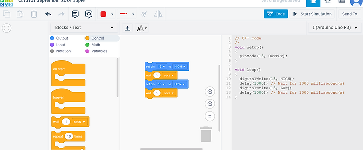
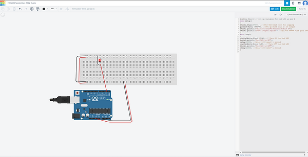
After that, I opened the code editor and selected the "Block + Text", to work on the block programming and reveal the Arduino code generated by the code blocks. Under the Out block category, I set pin 0 to HIGH block and changed the pin number to 13. In the text editor portion, you first see the code’s setup() function, which helps set up everything your program needs to run. This function runs once when the program starts up and contains everything within its curly braces { }. Notice that in our setup function, pin 13 is configured as an output, which prepares the Arduino to send signals to the pin, rather than listen. The main body of the program is inside the loop() function, indicated by another set of curly braces { }. This part of the code will execute on repeat, so long as the Arduino has power. The output command used to send signals to digital pins is called digitalWrite(). This function sets a pin HIGH or LOW, respectively on or off. Under the control block category, I connected the "wait for 1 sec" and added it under the first block. Under the output block category, I placed the "set pin 0 to HIGH" under the previous blocks and changed the pin number to 13 and state from "HIGH" to "LOW". Under the control block where it says "wait for 1 sec", I connected it under the first block and then ran the simulation. When running the simulation, I noticed the LED lights started blinking form on to off.
Step 2: Circuit Building, and Displaying Messages
Objectives
-
To familiarize with hardware components for course project
-
To learn how to build circuits with LEDs (Light Emitting Diode)
-
To learn how to program LEDs
-
To learn how to initialize the Serial Monitor
-
To learn how to send messages to the Serial Monitor
Next step of the project was to understand the tools that I were going to use for the remainder on the project.
-
Active Buzzer: A buzzer is a tiny speaker. It utilizes the concept of piezoelectricity which is an effect where certain crystals will change shape when you apply electricity to them. By applying an electric signal at a particular frequency, the crystal can output sound. Just like the LED, the buzzer is polarized, and it will only work when the ends are connected in a certain way. Your UCTRONICS kit includes both the active buzzer and passive buzzer. The active buzzer is required for the kit and you can identify it as it as a sticker on the top and a black coating on the bottom.
-
Resistor (10kΩ): When working with LEDs you will want to use a resistor, which helps limit the current to prevent the LED from burning itself out. For just one LED you will be safe not using a resistor. The colored stripes identify the resistor’s value. Your UCTRONICS kit conveniently labels the film of resistors to quickly identify the desired resistor. The electrical resistance of a resistor is measured in ohms and is represented by the Greek letter omega: Ω. Unlike the LED, a resistor is not polarized. You can learn more about the concept of resistance in the Tinkercad skill builder lesson on Ohm’s Law.
-
Photoresistor: Is a two-terminal, resistive component that increases or decreases its resistance depending on the light it senses. As more light shines of the sensor’s head, the resistance between its two terminals decreases. By combining the photocell with a resistor, we can create a voltage divider that produces a voltage dependent on the photocell's resistance. The Arduino can then read the variable voltage through the analog to digital converter.
-
Ultrasonic Sensor: An electronic device with two transducers that are used to detect an object within its range. The range of the sensor is from 3 cm to 3 m. When activated, one transducer sends a burst of ultrasounds by converting electric pulses into sound waves emitting them with frequency 40 kHz above the human hearing threshold. The other transducer other listens for the echo of the ultrasounds to bounce off an obstacle and come back. The sensor measures the round-trip time between the outburst of ultrasound and the reception of the echo. With the known round-trip times and speed of sound, the ultrasonic device can measure the distance that the sound traveled. We will use the ultrasonic distance sensor that has pins. The VCC pin is the operating voltage pin and the GND pin is the ground pin. The Trig pin is used to output the burst of ultrasounds and the Echo pin is used to read the returning echo from a nearby obstacle. The pins and technique described is illustrated in the figure below:
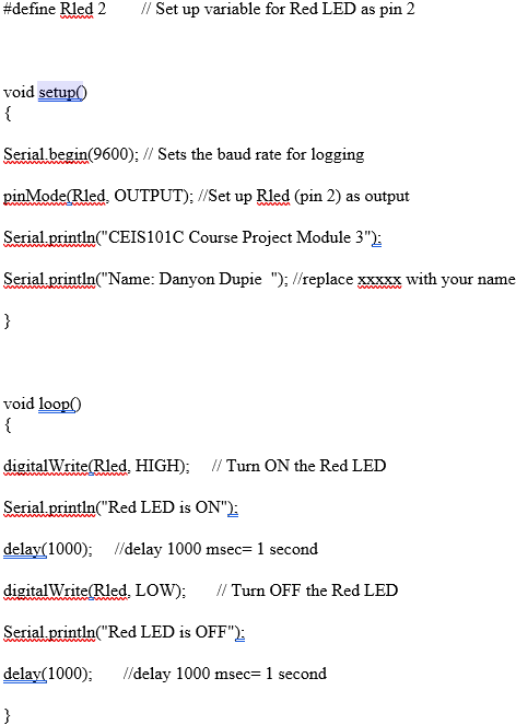
For this part of the project, I took the same design from step 1 but I started using C++. C++ is used for programming Arduino projects. When you create circuits with Tinkercad, you can use C++ to write code that controls electronic components, like lights or motors.
What I learned is that, for the Arduino to be able to send messages, it needs to establish a new communication channel with Serial.begin() inside the setup() function. The number inside the Serial.begin parenthesis is called an argument and it tells the Arduino how fast to communicate the messages. In this case, the baud rate is 9600 bits per second. Inside the loop() function the Serial.println() sends the data to the monitor over the USB cable. When changing the delay amount from 1000 to 100 and re-run the sketch, the blinking changes.
Code I ran
.png)
Step 3: Adding Door Sensor to Smart Home Security System
Objectives
-
To learn how to connect multiple LEDs to the Arduino Board
-
To learn how to connect a buzzer to the Arduino Board
-
To learn how to use a wire to emulate an open or closed door
-
To integrate an alarm into a security system
-
To familiarize with conditional programming instructions
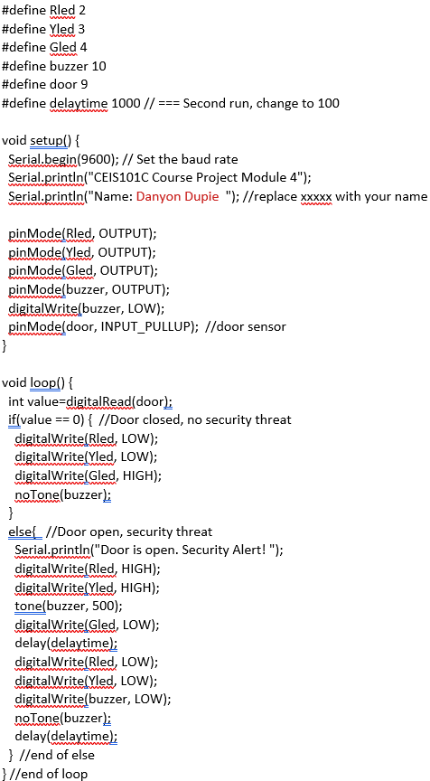
For step 3 of the project, I added a Yellow LED light where I connect pin 3 on the Arduino Board and the shorter lead to the breadboard's ground (-) rail and a green LED light where I connect pin 4 on the Arduino Board and the shorter lead to the breadboard's ground (-) rail. Next I added the passive buzzer to the breadboard and connect the left wire of the buzzer to pin 10 and the right wire of the buzzer to the negative (-) part of the breadboard. After that, I added a slidewitch and connect one end of a blue wire to pin 9 on the Arduino Board and the other end to terminal 1 of the switch, I connect a black wire from the common (middle) pin on the switch to the ground on the breadboard. When the swithc is in the left position, this represents a closed door. This will activate the green LED (Picture 1) to turn on and indicate that the home is secure and safe. If the swtich is moved to the right position while the code is running, then it will emulate an open door. This will activate the flashing red and yellow (Picture 3).
This is the code that I ran:


Step 4:
Adding Distance Sensor to Smart Home System
and Conducting Data Analysis
Objectives
-
To learn how to connect an ultrasonic range finder to the Arduino board
-
To learn how to write code that uses an ultrasonic range finder
-
To learn how to write code that makes the buzzer produce sounds
-
To learn how to display data to the Toggle plotter
-
To practice analyzing data generated by sensors
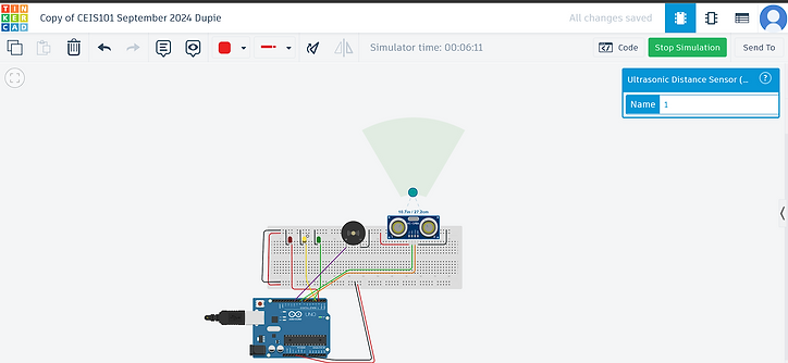
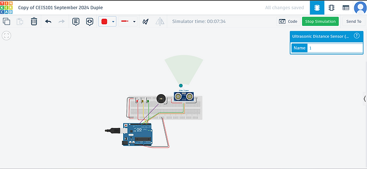
For step 4 of the project, I used a ultrasonic sensor to the smart home security prototype. You can remove the door sensor circuit as the motion sensor is more robust and generates useful data for the smart home system. When the ultrasonic sensor is activated, it sends a burst of ultrasound and waits for the echo to bounce off an obstacle and return. The time between the ultrasound outburst and the echo's reception can be measure. Based on the distance the ultrasonic sensor detects, the following conditions will be activated:
-
The buzzer tone will change as the object gets closer to the ultrasonic sensor (example: Home Entrance)
-
The Green LED (Picture 1) indicates no security risk, and an out-of-range (example: object is less than 12 inches away) message will be display on the serial monitor
-
The Yellow LED (Picture 2) will indicate a warning (example: Object is between 6 and 12 inches) message of a possible intruder.
-
The Red LED (Picute 3) will indicate high security risk (example: object is less than 6 inches away).
When I add the Ultrasonic sensor to the breadboard, I had to connect the Vee wire to 5v from the Arduino board, the GND wire connects to GND from the Arduino board, the Trig pin connects to pin 8 from the Arduino board, and the echo pin connects to pin 7 from the Arduino board.
After doing that I opened text mode in Tinkercad and ran this code:
#define trigPin 8
#define echoPin 7
#define Rled 2
#define Yled 3
#define Gled 4
#define buzzer 10
void setup() {
Serial.begin(9600);
Serial.println("CEIS101C Course Project Module 5");
Serial.println("Name: Danyon Dupie"); //replace xxxxx with your name
pinMode(trigPin, OUTPUT);
pinMode(echoPin, INPUT);
pinMode(Rled, OUTPUT);
pinMode(Yled, OUTPUT);
pinMode(Gled, OUTPUT);
pinMode(buzzer, OUTPUT);
}
void loop() {
long duration, distance, inches;
digitalWrite(trigPin, LOW);
delayMicroseconds(2);
digitalWrite(trigPin, HIGH);
delayMicroseconds(10);
digitalWrite(trigPin, LOW);
// Read the echo signal
//Read duration for roundtrip distance
duration = pulseIn(echoPin, HIGH);
//Convert duration to distance in units of inches
distance = (duration /2) * 0.0135 ;
if (distance <= 12) { //Outer IF statement units of inches
if (distance <=6){ //Alert range condition
digitalWrite(Rled, HIGH); //Alert green LED on
digitalWrite(Yled, LOW);
digitalWrite(Gled, LOW);
}
if (distance <12 and distance > 6) { //Warning range condition
digitalWrite(Rled, LOW);
digitalWrite(Yled, HIGH); //Warning yellow LED on
digitalWrite(Gled, LOW);
}
//==================== Beeping Rate Code Start ======
tone(buzzer,500);
for (int i= distance; i>0; i--)
delay(10);
noTone(buzzer);
for (int i= distance; i>0; i--)
delay(10);
//==================== Beeping Rate Code End =======
}
else{ //Safe range condition
digitalWrite(Rled, LOW);
digitalWrite(Yled, LOW);
digitalWrite(Gled, HIGH); //Safe distance green LED on
noTone(buzzer);
}// end of outer IF statement
//Filter noise to show readings only less than
//the sensor range of 13 ft = 156 inches
if (distance < 156)
//print distance to show in Serial Monitor
Serial.println(distance);
//pause program to stabilize ultrasonic sensor readings
delay(100);
} //end of loop
When click on the ultrasonic sensor, each LED color lights up based on the distance read by the ultrasonic sensor.


Step 5:
Adding Automated Light to Smart Home System
Objectives
-
To learn how to connect a light sensor to the Arduino board
-
To learn how to write code that uses a light sensor
-
To learn how to write code that turns on the light based on the reading from the light sensor
For the final step of the project, I add a Blue LED light to the breadboard where the longer lead wire connects to pin 6 on the Arduino Board and the shorter lead wire connects to the breadboard's ground (-) rail. Then I added a 10 kΩ resistor. After that, I ran this code:
#define trigPin 8
#define echoPin 7
#define Rled 2
#define Yled 3
#define Gled 4
#define buzzer 10
#define photocell A0
#define autoLight 6
void setup() {
Serial.begin(9600);
Serial.println("CEIS101C Course Project Module 6");
Serial.println("Name: Danyon Dupie"); //replace xxxxx with your name
pinMode(trigPin, OUTPUT);
pinMode(echoPin, INPUT);
pinMode(Rled, OUTPUT);
pinMode(Yled, OUTPUT);
pinMode(Gled, OUTPUT);
pinMode(buzzer, OUTPUT);
pinMode(autoLight, OUTPUT);
}
void loop() {
//=== Automated Light ===
//read from the light sensor to determine the condition
int value=analogRead(photocell);
//uncomment the line below, open the serial plotter to see the effect on the light
//Serial.println(value);
if (value > 450) {
digitalWrite(autoLight, HIGH);
Serial.println("The automated light is ON");
}
else {
digitalWrite(autoLight, LOW);
}
//==== Distance Sensor ===
long duration, distance, inches;
digitalWrite(trigPin, LOW);
delayMicroseconds(2);
digitalWrite(trigPin, HIGH);
delayMicroseconds(10);
digitalWrite(trigPin, LOW);
// Read the echo signal
//Read duration for roundtrip distance
duration = pulseIn(echoPin, HIGH);
//Convert duration to distance in units of inches
distance = (duration /2) * 0.0135 ;
if (distance <= 12) { //Outer IF statement units of inches
if (distance <=6){ //Alert range condition
Serial.println("Alert! Possible Intruder.");
digitalWrite(Rled, HIGH); //Alert green LED on
digitalWrite(Yled, LOW);
digitalWrite(Gled, LOW);
}
if (distance <12 and distance > 6){ //Warning range condition
digitalWrite(Rled, LOW);
digitalWrite(Yled, HIGH); //Warning yellow LED on
digitalWrite(Gled, LOW);
}
//==================== Beeping Rate Code Start ======
tone(buzzer,500);
for (int i= distance; i>0; i--)
delay(10);
noTone(buzzer);
for (int i= distance; i>0; i--)
delay(10);
//==================== Beeping Rate Code End =======
}
else{ //Safe range condition
digitalWrite(Rled, LOW);
digitalWrite(Yled, LOW);
digitalWrite(Gled, HIGH); //Safe distance green LED on
noTone(buzzer);
}//end of outer IF statement
delay(100); //pause program to stabilize sensor readings
} //end of loop
Since the value of the light sensor changes according to the intensity of the amount of light it receives, its voltage will also change accordingly. The Arduino board has analog inputs that can read an input voltage and convert it into a number. Thus, the number is directly proportional to the intensity of light received by the light sensor. Based on the readings that will be shown in the Serial Monitor, we will control the condition at which the automated light will turn on. When sliding the photoresistor on dark, the blue LED light would turn on. Sliding the photoresistor on light, the blue LED light would turn off.

